From particles to rigid bodies: angular quantities
A rigid body is an idealized extended object whose shape and size do not change while forces act. Real objects deform slightly, but the model is powerful whenever that deformation is negligible. Unlike a particle, a rigid body can both translate—its centre of mass moves—and rotate about an axis.
Rotation is described using angular displacement , angular velocity , and angular acceleration . Angles must be measured in radians when they are used in rotational equations. Choose one rotational sense as positive; viewed along a fixed axis, counterclockwise is commonly positive and clockwise negative.
For rotation about a fixed axis, all points share the body's angular displacement, angular velocity, and angular acceleration. Points farther from the axis have greater tangential speed: , where is perpendicular distance to the axis. Angular displacement is treated as a signed angle here. Angular velocity and angular acceleration can also be represented by axial vectors using the right-hand rule; a finite rotation in general three-dimensional motion is not an ordinary vector.
Key terms
- Rigid body
- An idealized extended object whose distances between all pairs of points remain constant.
- Angular displacement
- The angle through which a body turns, measured in radians.
- Angular velocity
- The rate of change of angular displacement.
- Angular acceleration
- The rate of change of angular velocity.
- Axis of rotation
- The line about which the body rotates.
Worked examples
Revolutions to angular velocity
A turntable completes revolutions in at a steady rate. Find its angular displacement and angular velocity.
- 1Convert revolutions to radians: .
- 2Use .
- 3Keep in the calculator until the final step: to two significant figures.
Answer: and .
Different radii, different linear speeds
A rigid disk rotates at . Compare the speeds of points at and from the axis.
- 1At , .
- 2At , .
- 3The outer point is three times farther from the axis and therefore moves three times faster.
Answer: The speeds are and ; both points share the same angular velocity.
Rules and formulas
Radian definition
- angular displacement ()
- signed arc displacement, measured in the chosen positive rotational sense ()
- distance from the axis ()
Average angular velocity
- average angular velocity ()
- elapsed time ()
Average angular acceleration
- average angular acceleration ()
- change in angular velocity ()
Angular-to-linear relationships
- tangential speed ()
- signed tangential acceleration in the chosen positive rotational sense ()
- centripetal acceleration magnitude, directed toward the axis ()
Rotational kinematics with constant angular acceleration
For rotation about a fixed axis, constant-angular-acceleration equations mirror the familiar linear equations. The mapping is , , , and .
The equations apply only while angular acceleration is constant. Before substituting, state a positive rotational direction and attach signs to angular velocities and angular acceleration. A rotating object can slow down while its angular velocity is positive if its angular acceleration is negative.
Angular-displacement graphs use the same gradient ideas as linear-motion graphs: the gradient of a -against- graph is , while the gradient of an -against- graph is . The signed area under an -against- graph is angular displacement.
Key terms
- Uniform angular acceleration
- Angular acceleration that remains constant over the interval considered.
- Initial angular velocity
- Angular velocity at the chosen start of the interval.
- Angular-displacement graph
- A graph whose gradient gives angular velocity.
Worked examples
Speeding up a flywheel
A flywheel speeds up uniformly from to in . Find and .
- 1.
- 2With constant , average angular velocity is .
- 3.
Answer: and .
Braking a fan
A fan rotating at comes uniformly to rest in . Find its angular acceleration and the number of turns made.
- 1Take the initial rotation as positive.
- 2.
- 3.
- 4Number of turns , so the fan completes about turns.
Answer: and the fan turns revolutions.
Rules and formulas
Angular velocity–time
- initial angular velocity ()
Angular displacement–time
- angular displacement ()
No-time equation
- constant angular acceleration ()
Mean-angular-velocity equation
- elapsed time ()
Torque, lever arms, couples, and the line of action
A force can change translational motion and also produce a turning effect. Torque about a chosen point or axis measures this turning effect. It depends on the force, the distance from the axis, and the angle between the position vector and the force.
For forces in a plane perpendicular to the chosen axis, the torque magnitude about that axis is . Here runs from the pivot to the force point in that plane, and is the perpendicular distance from the pivot to the force's line of action. Assign the rotational sign separately. A force whose line of action passes through the axis gives zero torque about that axis. In three dimensions, torque about an axis is the component of the torque vector along that axis, not generally the vector's full magnitude.
Torque direction follows the right-hand rule. In a two-dimensional problem, assign clockwise and counterclockwise torques opposite signs. A couple is a pair of equal, opposite, parallel forces with different lines of action: its resultant force is zero but its torque is not.
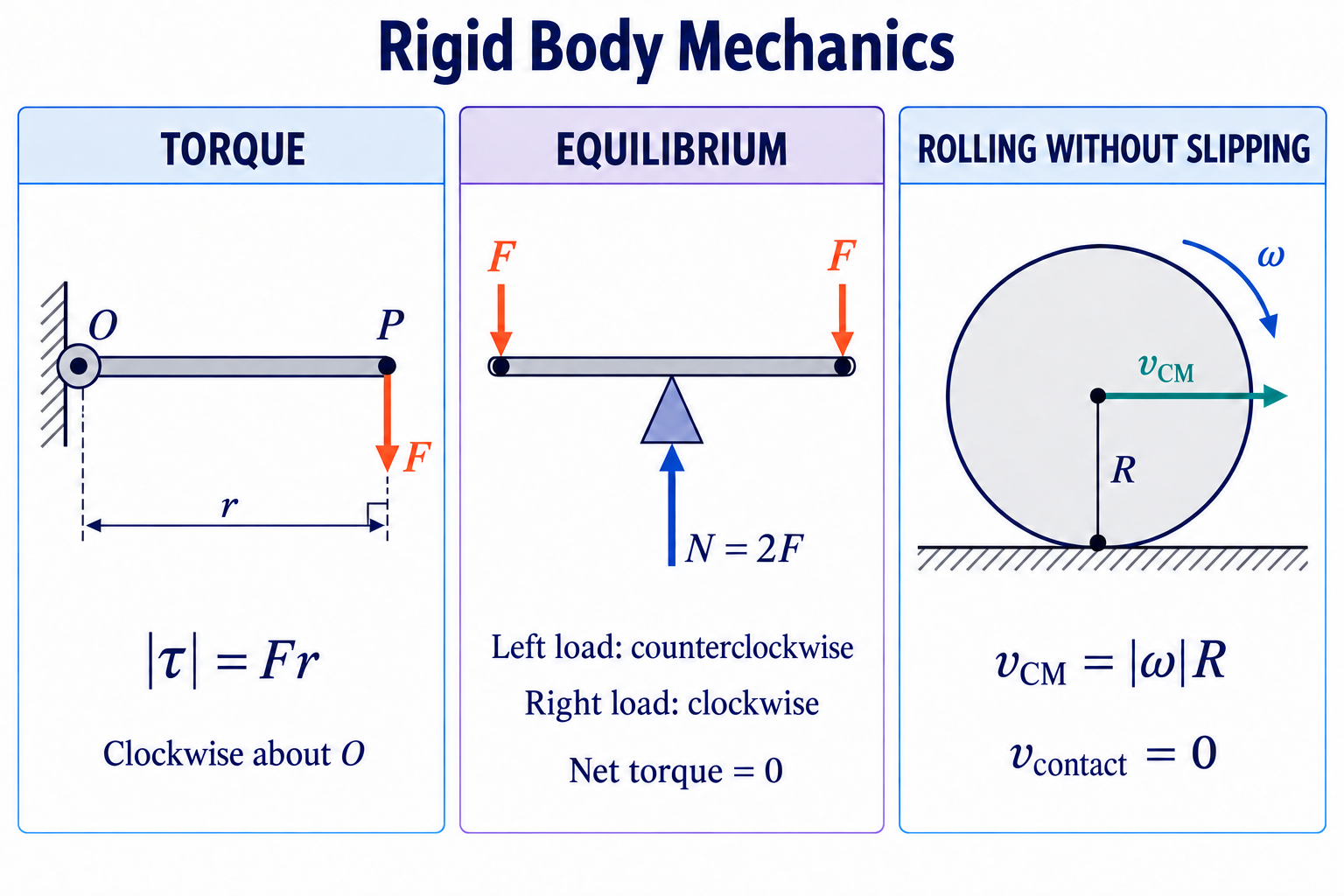 Qualitative schematics. Left: the force is perpendicular to the beam, so its lever arm is r. Centre: equal loads act at equal distances from the pivot of an ideal weightless beam; the upward reaction balances both loads. Right: rolling without slipping on stationary ground; speeds are measured relative to the ground.Axis-first checklist
Torque: Draw the force's complete line of action, then the shortest perpendicular from the pivot to that line. Its length is , giving for . A downward force applied to the right of a pivot produces clockwise torque; a downward force to its left produces counterclockwise torque.
Equilibrium: Two downward loads on opposite sides balance rotationally when , provided no other moment acts. Full static equilibrium also requires ; for an ideal weightless beam, the upward support force is .
Rolling: A wheel rolling right without slipping on a stationary surface rotates clockwise. Its centre speed is ; the instantaneous contact point has zero velocity relative to that surface.
Key terms
- Torque
- The turning effect of a force about a chosen point or axis.
- Line of action
- The infinite straight line in the direction of a force through its point of application.
- Perpendicular lever arm
- The shortest distance from the axis to the force's line of action.
- Couple
- Two equal, opposite, parallel forces with different lines of action, giving zero resultant force and a non-zero torque.
Worked examples
Opening a door efficiently
A force acts perpendicular to a door from its hinge. Find the torque.
- 1The force is perpendicular, so .
- 2.
- 3The rotational direction must be stated from the diagram or sign convention.
Answer: The torque magnitude is .
Angled force on a spanner
A force is applied from a bolt at to the spanner. Find the torque magnitude.
- 1The quoted angle is between the position vector along the spanner and the force.
- 2Use the perpendicular component: .
- 3.
Answer: The torque magnitude is .
Rules and formulas
Torque about a chosen origin (vector extension)
- position vector from the chosen origin to the force application point ()
- applied force ()
Planar torque magnitude about the perpendicular axis
- angle between position vector and force
- perpendicular lever arm ()
Torque of a couple
- perpendicular separation of the two force lines ()
Rotational equilibrium, centre of mass, and stability
In the planar models used here, complete mechanical equilibrium requires both zero resultant external force and zero resultant external torque: and . Force balance prevents centre-of-mass acceleration; torque balance about the axis perpendicular to the plane prevents angular acceleration for constant . When the resultant force is zero, changing the origin does not change the resultant torque.
In a uniform gravitational field, the resultant weight can be treated as acting through the centre of mass, which then coincides with the centre of gravity. Choosing a pivot through an unknown support force often eliminates that force's torque and simplifies the equation.
Under gravity alone, a supported body's limiting balance occurs when the vertical through its centre of mass reaches an edge of its base; beyond that edge, its weight produces an overturning torque. A wider base and lower centre of mass generally improve this gravitational stability. If additional forces act, find the tipping threshold by balancing all torques about the candidate base edge: an applied push can cause tipping while the centre-of-mass projection is still inside the base.
Key terms
- Translational equilibrium
- A state in which the vector sum of external forces is zero.
- Rotational equilibrium
- A state in which the sum of external torques about an axis is zero.
- Centre of mass
- The mass-weighted average position of an object's matter.
- Base of support
- The ground-contact support region; under gravity alone, the weight's line of action must lie within it for static support without tipping.
Worked examples
Balancing a seesaw
A child sits left of a pivot. Where should a child sit on the right for equilibrium?
- 1Take torques about the pivot so the pivot force has zero lever arm.
- 2Set opposite torque magnitudes equal: .
- 3Solve . Check that clockwise and counterclockwise torques are both .
Answer: The second child should sit to the right of the pivot.
Force needed to tip a crate
A crate weighs , is wide, and has its centre of mass midway across the base. A horizontal force is applied above the floor. Assume that the floor provides enough static friction to prevent sliding. Find the force that just begins to tip the crate.
- 1At impending tip, choose the lower edge toward which the horizontal force points as the pivot, opposite the face where the push is applied. The other edge is about to lift from the floor.
- 2The weight's lever arm is half the width: .
- 3Balance torques: , giving .
Answer: The threshold force is approximately , assuming the crate does not slide first.
Rules and formulas
Translational equilibrium
- external force ()
Rotational equilibrium
- signed external torque about the chosen axis ()
Centre of mass for discrete masses
- centre-of-mass position ()
Moment of inertia: how mass distribution resists rotation
The moment of inertia measures how strongly a body's mass distribution resists angular acceleration about a specified axis. It is the rotational analogue of mass, but it is not determined by total mass alone: moving mass farther from the axis increases in proportion to .
For point masses, add . For a continuous body, the same idea becomes . Always state the axis because the same object has different moments of inertia about different axes.
IB guidance states that the moment-of-inertia expression for a specific mass distribution will be supplied when needed. Use it with the stated shape and axis; the values below are reference examples, not an additional memorization list. Calculating for point masses remains part of the core. The continuous-body integral and parallel-axis theorem explain useful relationships between inertia results. The parallel-axis theorem, , shifts a known value about a centre-of-mass axis to a parallel axis a distance away.
Key terms
- Moment of inertia
- A measure of rotational inertia that depends on mass distribution and the chosen axis.
- Point-mass model
- A model in which each object's dimensions are negligible compared with its distance from the axis.
- Parallel-axis theorem
- A relationship for shifting a centre-of-mass moment of inertia to a parallel axis.
Worked examples
Two point masses on a light rod
Two masses are each from a central axis. The connecting rod has negligible mass. Find .
- 1Treat each object as a point mass: .
- 2.
- 3Doubling each radius would multiply the moment of inertia by four.
Answer: .
Rod about one end
A uniform thin rod has mass and length . Use the parallel-axis theorem to find its moment of inertia about an axis through one end perpendicular to the rod.
- 1About its centre, .
- 2The end axis is from the centre.
- 3.
Answer: The rod's moment of inertia about one end is .
Rules and formulas
Discrete masses
- perpendicular distance of mass i from the axis ()
Continuous mass distribution
- infinitesimal mass element ()
Parallel-axis theorem
- separation of the parallel axes ()
Thin uniform ring or hoop about its central symmetry axis
- radius ()
Uniform solid disk or cylinder about its central symmetry axis
- total mass ()
Uniform thin rod about a perpendicular axis through its centre
- rod length ()
Uniform thin rod about a perpendicular axis through one end
- moment of inertia ()
Uniform solid sphere about an axis through its centre
- sphere radius ()
Rotational dynamics and angular impulse
For a rigid body rotating about a fixed axis, the rotational form of Newton's second law is . The left side is the resultant external torque, not one selected applied torque. A larger produces a smaller angular acceleration for the same net torque.
Solve rotational-dynamics problems as you solve linear ones: isolate the body, draw all external forces, choose the axis and positive sense, calculate each signed torque, and only then connect the resultant torque to angular acceleration.
The resultant external torque acting over time provides the net angular impulse. About the same fixed axis, , where is the signed angular-momentum component about that axis. For constant net torque, ; for a varying net torque, use its time-average in this product. The signed area under a net external torque–time graph therefore equals the change in the system's angular momentum about the axis.
Key terms
- Resultant torque
- The signed sum of all external torques about the chosen axis.
- Angular impulse
- The time integral of a torque. The resultant external angular impulse equals the system's change in angular momentum about the same fixed axis.
- Fixed-axis rotation
- Rotation in which the direction and position of the axis remain fixed.
Worked examples
Angular acceleration of a disk
A uniform solid disk of mass and radius rotates about its fixed central axis perpendicular to its face. It experiences a net torque of about this axis. Find its angular acceleration.
- 1For a solid disk, .
- 2Apply .
- 3, in the direction of the resultant torque.
Answer: The angular acceleration is .
Angular impulse on a wheel
A constant resultant external torque of acts for about a wheel's fixed axis. Its moment of inertia about that axis is , and it is initially at rest. Taking the torque direction as positive, find its final angular velocity.
- 1Angular impulse is .
- 2This equals .
- 3With , .
Answer: The final angular velocity is .
Rules and formulas
Rotational Newton's second law
- resultant external torque ()
- moment of inertia about the axis ()
Net external angular impulse about a fixed axis
- net external angular impulse about the chosen fixed axis ()
- signed resultant external torque about that axis ()
- change in the system's signed angular-momentum component about that axis ()
Constant net-torque angular impulse
- change in the system's signed angular-momentum component about the chosen fixed axis ()
Angular momentum and its conservation
Angular momentum is defined relative to a chosen origin or axis. For a particle, the optional vector form is , with measured from that origin. For rotation about a fixed axis, gives the signed component of angular momentum along that axis. About a principal axis, the angular-momentum and angular-velocity vectors are parallel, so the full angular-momentum magnitude is . In general three-dimensional rotation these vectors need not be parallel.
About a fixed origin in an inertial frame, external torque changes angular momentum: . If the resultant external torque is zero, the total angular-momentum vector is conserved; a negligible torque gives approximate conservation. For the fixed-axis scalar model, zero net external torque about the axis conserves the total signed angular-momentum component about that axis. Internal interactions can transfer angular momentum between parts without changing the system total.
Conservation of angular momentum does not automatically imply conservation of kinetic energy. When rotating objects stick together, angular momentum can be conserved while mechanical energy is transferred to internal energy, sound, and deformation.
Key terms
- Angular momentum
- A rotational quantity defined relative to an origin or axis and changed by external torque.
- External torque
- Torque exerted on the chosen system by objects outside its boundary.
- Isolated rotational system
- A system with negligible resultant external torque during the interval considered.
Worked examples
A skater pulls in their arms
A skater rotates at with . Pulling in the arms reduces the moment of inertia to . Find the new angular velocity if external torque is negligible.
- 1Conserve angular momentum: .
- 2.
- 3The skater's muscles do work while pulling inward, so rotational kinetic energy can increase even though angular momentum is constant.
Answer: The new angular velocity is .
Two disks stick together
A disk with rotates at . It lands coaxially on a stationary disk with , and they rotate together about their common fixed vertical axis. Assume that external angular impulse about this axis is negligible during contact. Find the final angular velocity and comment on rotational kinetic energy.
- 1Angular momentum before is .
- 2After contact, , so .
- 3, while .
Answer: ; angular momentum about the common axis is conserved, while rotational kinetic energy decreases by .
Rules and formulas
Particle angular momentum
- linear momentum ()
Angular-momentum component about a fixed axis
- signed angular-momentum component about the chosen fixed axis ()
Torque and angular momentum about a fixed inertial origin
- resultant external torque about that fixed origin ()
Angular-momentum conservation
- total signed angular-momentum component of the chosen system about the same fixed axis ()
Rotational work, kinetic energy, and power
For rotation about a fixed axis, use the signed torque component about that axis. A constant torque does work , which is negative when the torque opposes the rotation. More generally, rotational work is the signed area under a torque–angle graph: .
For a rigid body rotating about a fixed axis, , where is the signed angular-momentum component about that axis. With constant , the net work of the external torques about the axis equals the change in rotational kinetic energy. This energy method can connect initial and final states without first finding angular acceleration or time.
Rotational power is the rate of doing rotational work. For rotation about a fixed axis, uses signed torque and angular velocity about that axis; a resisting torque gives negative power. For a real machine, transfers into unintended pathways such as heating, sound, and deformation reduce useful mechanical-output efficiency below .
Key terms
- Rotational work
- Energy transferred by a torque through an angular displacement.
- Rotational kinetic energy
- The kinetic energy associated with a body's rotation.
- Rotational power
- The rate at which a torque transfers energy.
Worked examples
Work done by a motor torque
A constant motor torque of turns a flywheel through . The flywheel has and starts from rest. Neglect losses and find its final angular velocity.
- 1Work done is .
- 2Set work equal to rotational kinetic energy: .
- 3.
Answer: The final angular velocity is to two significant figures.
Instantaneous rotational power
A shaft delivers a torque of while rotating at . Find the mechanical power.
- 1Use because torque and angular velocity act about the same axis.
- 2.
- 3This is the instantaneous mechanical output before any later transmission losses are included.
Answer: The mechanical power is .
Rules and formulas
Work by constant torque
- rotational work ()
Work by variable torque
- angular position ()
Fixed-axis rotational kinetic energy
- rotational kinetic energy ()
- signed angular-momentum component about the rotation axis ()
- moment of inertia about that same axis ()
Rotational power
- instantaneous power ()
Rolling without slipping: translation and rotation together
An axisymmetric rigid wheel or cylinder rolling along a straight, stationary surface has translational kinetic energy of its centre of mass and rotational kinetic energy about that centre. For rolling without slipping, , where is speed. Choose matching positive linear and rotational senses so the signed tangential accelerations satisfy . For free gravity-driven rolling down a fixed incline, the acceleration formula below also assumes no applied driving torque, negligible rolling resistance, and sufficient static friction to prevent slipping.
For rolling without slipping on a stationary surface, the material point at contact is instantaneously at rest relative to that surface. The point diametrically opposite contact—at the top of the wheel when the surface is horizontal—has speed relative to the ground. These values come from vector addition of the centre-of-mass velocity and the velocity due to rotation about the centre.
Static friction can provide the torque needed to start or maintain rolling without dissipating mechanical energy at an ideal, non-slipping contact. Its direction is determined from the tendency to slip, not by memorizing that friction always points uphill or downhill.
Key terms
- Rolling without slipping
- Rolling in which the contact point has zero instantaneous velocity relative to the surface.
- Centre-of-mass motion
- Translation of the body's mass-weighted average position.
- Static friction
- A contact force that prevents relative sliding at the contact point.
Worked examples
Solid cylinder rolling down a height
A solid cylinder rolls without slipping from rest through a vertical drop of . Neglect losses and find its speed.
- 1Use .
- 2For a solid cylinder, , and no slipping gives .
- 3Therefore .
- 4 for .
Answer: The cylinder's speed is approximately .
Speeds at the top and contact point
A bicycle wheel rolls right without slipping with centre speed . Find the instantaneous ground-frame speeds of the top and bottom points.
- 1No slipping gives rim speed relative to the centre .
- 2At the top, the translational and rotational velocities point right and add.
- 3At the bottom, they are equal and opposite and cancel instantaneously.
Answer: Top point: right; contact point: .
Rules and formulas
No-slip speed constraint
- centre-of-mass speed ()
No-slip acceleration constraint
- signed centre-of-mass acceleration along the straight surface, with matching positive linear and rotational senses ()
Total rolling kinetic energy
- total kinetic energy ()
Free gravity-driven rolling down a fixed incline (no slip or losses)
- incline angle
Coupled systems and an IB problem-solving workflow
Many HL problems couple a translating object to a rotating pulley, disk, or wheel. The string tension may be different from the hanging weight because some of the weight's effect accelerates the mass and some produces angular acceleration of the rotating body.
Use the connection constraint appropriate to the model. A taut string that does not slip on a fixed-axis pulley has tangential acceleration when positive string and pulley senses are matched. A wheel rolling without slipping along a straight, stationary surface has . Apply linear dynamics to translating parts, rotational dynamics to rotating parts, and keep the axis and sign convention consistent.
A strong IB solution begins with a system boundary and axis, a force diagram for each body, and a list of constraints. It then uses symbolic equations before numerical substitution, carries guard digits, includes units, and checks limiting cases such as a negligible pulley inertia.
Key terms
- Coupled system
- A system whose translating and rotating parts are linked by a geometric or force constraint.
- No-slip string constraint
- For a taut string on a fixed-axis pulley without slipping, the signed tangential string acceleration equals Rα when positive senses are matched.
- Limiting-case check
- Testing a result in an extreme but meaningful case to reveal sign or algebra errors.
Worked examples
Hanging mass and massive pulley
A mass hangs from a light string wrapped around a fixed solid-disk pulley of mass and radius . The string does not slip and axle friction is negligible. Find the downward acceleration and string tension.
- 1For the mass, choose downward positive: .
- 2For the pulley, , with and . Therefore .
- 3Substitute: , so .
- 4Then .
Answer: downward and .
Rod falling about a hinge
A uniform rod of length is released from rest horizontally and swings downward about a frictionless hinge at one end. Find its angular speed when vertical.
- 1The centre of mass falls by , so the loss of gravitational potential energy is .
- 2For a rod about one end, .
- 3Conserve mechanical energy: .
- 4Cancel and solve: .
Answer: The angular speed is .
Rules and formulas
Coupled linear dynamics
- translating mass ()
Coupled rotational dynamics
- rotating body's moment of inertia ()
No-slip coupling
- pulley or wheel radius ()
Topic summary
- A rigid body may translate and rotate while its internal distances remain fixed in the model.
- For fixed-axis rotation, radians give signed arc displacement , tangential speed , and signed tangential acceleration .
- Constant-angular-acceleration equations require a stated sign convention and genuinely constant angular acceleration.
- Torque about an origin has the optional vector form . For planar forces about the perpendicular axis, its magnitude is ; give the rotational sense a sign.
- A force whose line of action passes through the axis produces zero torque about that axis.
- In a planar problem, complete equilibrium requires both and zero resultant torque about the perpendicular axis.
- Under gravity alone, a lower centre of mass and wider base generally improve stability. With additional forces, determine tipping by balancing all torques about a base edge and check that sliding does not occur first.
- Moment of inertia depends on both mass and its perpendicular distribution about the chosen axis.
- For fixed-axis rotation, the resultant external torque obeys .
- Net external angular impulse about a fixed axis equals the change in the system's angular-momentum component and is the signed area under the net external torque–time graph.
- For fixed-axis rotation, is the signed angular-momentum component about that axis; the system's total component is conserved when net external torque about the axis is zero or negligible.
- Angular-momentum conservation does not by itself guarantee conservation of rotational kinetic energy.
- For fixed-axis rotation, , , and , using signed torque and angular quantities about the same axis.
- For a balanced circular body rolling without slipping along a straight, stationary surface, .
- A rolling object generally has both translational and rotational kinetic energy.
- Static friction is determined by the tendency to slip and need not dissipate energy in ideal rolling.
- Coupled problems often require linear and rotational dynamics plus a connection constraint; use a no-slip relation only when the stated model warrants it.
- IB solutions should show the axis, system boundary, sign convention, symbolic equations, SI units, assumptions, and a physical reasonableness check.